Introduction
This document discusses how to set up the basic parameters of LED Walls.
NOTE: To learn more about the additional adjustable parameters of the LED Wall X control panels, please refer to the following document:
The LED Wall X Control Panels
Setting Up the LED Wall
Go to the LEDWALLS control board.
Selecting How Many LED Walls Are Used
With the On/Off button at the beginning of each row, you can turn on/off the LED Wall outputs used for the production:
NOTE: If you use only 1 video cable to connect to the LED processor, you still have to select as many LED walls as many signals you would like to send on that 1 cable.
Setting Up the Basic Parameters
The first step is specifying the Size, Curve Radius, Resolution, and - if needed - the Shape and Shape Mask of each LED Wall.
Select the LED Wall X control panels, head over to the Pin Values panel, and look for these parameters:
Size
Specify the exact dimensions of the LED Wall (Width/Height).
IMPORTANT: Size uses meters as the unit of measure.
Curve Radius
If using a curved LED Wall, specify the curve radius of the LED Wall.
IMPORTANT: Curve Radius uses meters as the unit of measure.
IMPORTANT: The Virtual LED Wall's curve is an arc of a regular circle.
Resolution
Specify the output resolution used for the LED Wall.
Shape
Aximmetry supports the following LED Wall shapes:
- Rectangle
- Triangle Top-Left (corner)
- Triangle Top-Right (corner)
- Triangle Bottom-Left (corner)
- Triangle Bottom-Right (corner)
NOTE: For custom-shaped LED Walls, do not adjust this parameter.
Shape Mask
Aximmetry supports the use of custom LED Wall shapes. Custom masks require a (preferably lossless) black-and-white image file (the white part defines the custom shape mask).
Shape Masks and Curve Radius can be used together.
NOTE: To learn more about supported image file formats, please refer to the following document:
Image
Checking of the LED Wall Settings
On the LED Wall X control panel select the Check monitor mode:
The Check monitor mode displays the checker pattern on each currently used LED Wall.
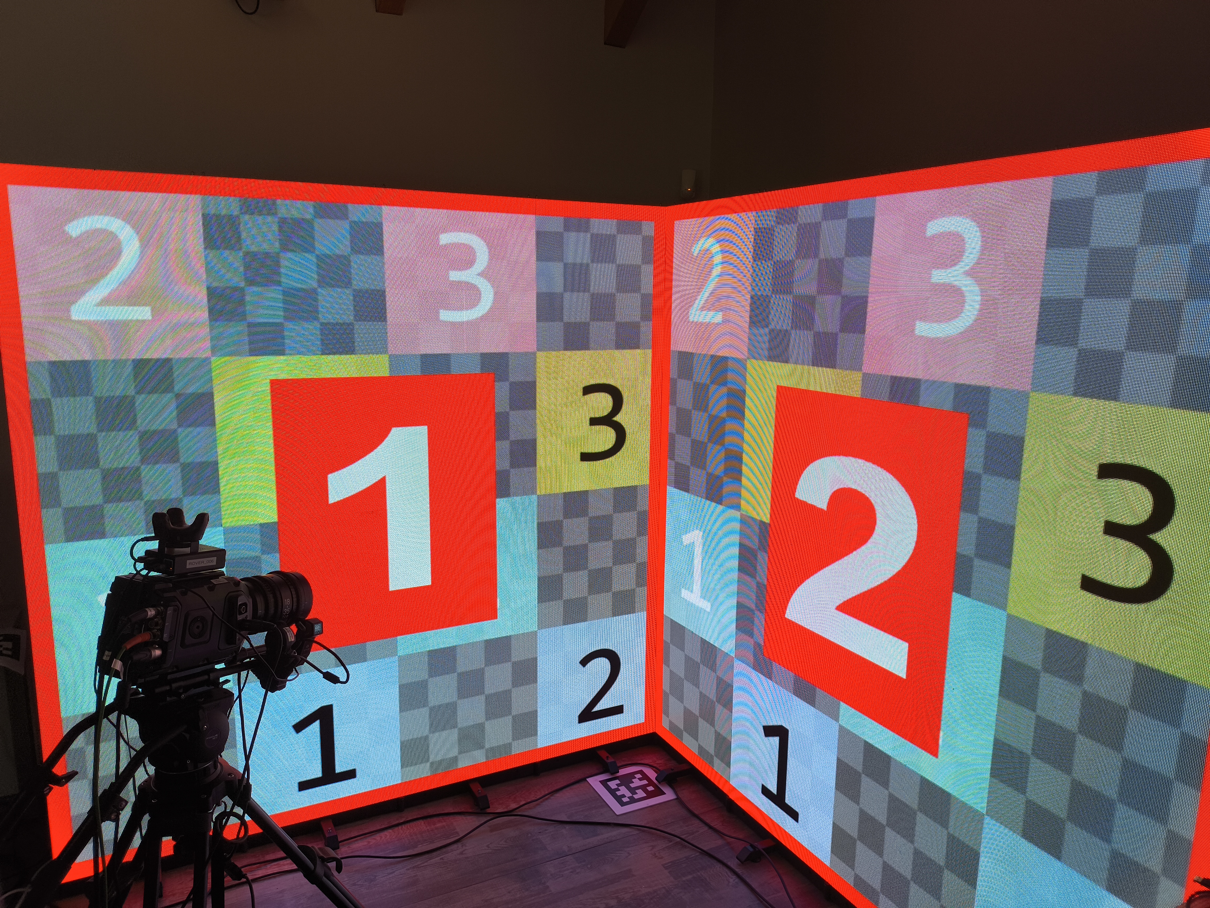
NOTE: Example of the checker pattern correctly displayed on two LED Walls of 2x2 meters in dimension per piece.
The settings are correct if:
- The big index numbers at the centers are the correct ones. (They match the LED Wall X control panel's number.)
- You can see the red border on all four edges of all LED walls. The border must be 5 cm thick everywhere. Use a measuring tape to check that.
- Each numbered square of the checker patterns has to be 50 cm x 50 cm. Use a measuring tape to check that.
- Each smaller light and mid grey checker patterns have to be 10 cm x 10 cm. Use a measuring tape to check that.
NOTE: The numbering of the checker pattern also reflects the dimensions of the LED wall in meters.


